
Application of Advanced Technologies in Excavation, Analysis, Consultation, and Reburial: The Alameda-Stone Cemetery in Tucson, Arizona
This post is part of Tech Week, which highlights a group of posts about specific…

By Carrie Fulton
If you attend any archaeology conference or glance through recent issues of journals, you will quickly see the extent to which photogrammetric documentation has become a part of an archaeologist’s toolkit. Take a few photos, import them to software, and hit go. Violà! You now have digital models of your site or object. Ok, so the steps are slightly more detailed, but with new technology, the interfaces and steps to producing accurate models are getting easier and less technical.
The benefits of digital recording are massive: increased speed of recording, preservation of three-dimensional information, geo-referenced data, digital preservation of contexts that are destroyed through the process of excavation, and easy dissemination of information. How can this technology be used effectively? And are there drawbacks? If so, how can they be mitigated?
Let’s look at the excavation and documentation of the remains of a late 18th-century ship discovered during the construction at the World Trade Center site in July 2010.
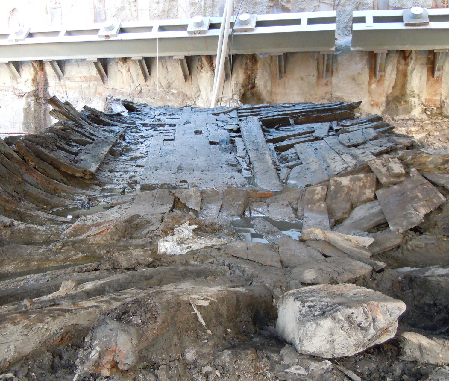
Figure 1: Remains of the World Trade Center Ship looking from the stern towards the retention wall. (Photo: K. Galligan)
Since the ship was found in one section of an active construction site, we had to move quickly so the timbers could be removed and construction could continue. Approximately 32 feet of the ship’s stern (back end) remained. However, a modern retention wall bisected the ship and destroyed evidence for much of the forward half of the ship except for a very small section of the bow (forward end) of the ship that was uncovered in August 2011 when the other side of the wall was cleared.
To capture the relationship between timbers we used laser scanning, photographs, videography, and sketches. This enabled us to give each timber a unique identification so that upon disassembly we could keep track of each piece and reconstruct the in situ relationship. Once removed from the site, we had more time to analyze the timbers, but the next step in the preservation of the ship hadn’t been determined. We were faced with the question: How do we record each timber accurately and quickly? We settled on an approach that combined traditional methods for documenting timbers with recent advances in photogrammetry to create three-dimensional digital recordings of the timbers.
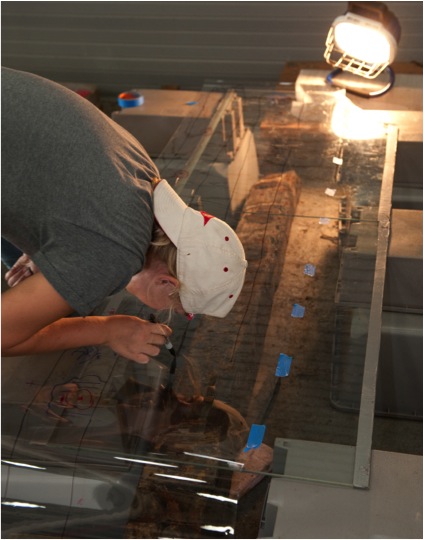
Figure 2: Making a 1:1 tracing of a frame. (Photo: D. Fulton)
Traditionally, nautical archaeologists record the dimensions by tracing the timbers in 1:1 reproductions or making scaled drawings of each face (Figure 2). The advantage of this approach is the close examination and documentation of each face, noting patterns in fasteners, tool patterns, and any biological growth that might be indicative of post-depositional processes. However, this method is extremely time consuming, and there is the possibility for dimensions to be distorted in tracing (due to parallax) or in condensing information into a scaled drawing.
For the best use of resources and time, we made 1:1 tracings of the two sides of the frames where the ceiling planking and the outer planking were attached. This allowed us to record the arrangement in nail patterns, which is crucial to answering questions about whether the ship timbers had been repaired. To document the curves of the frames that are difficult to render in two dimensions, we used photogrammetry to generate three-dimensional models. For all other timbers of the ship, we also used photogrammetry rather than tracings.
Each timber still had its own data sheet with notations for tool marks, measurements, marine growth, and any other information that might aid in the reconstruction of the ship and its life history. However, the timber is now preserved in a digital record as a three-dimensional model. Creating a model involved a three-step procedure:
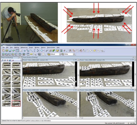
Figure 3: Drew Fulton photographs a frame which was imported into PhotoModeler Scanner.
STEP 1: Photograph the timber. For the version of PhotoModeler Scanner in 2010, stereo pairs of photographs were taken from each side of the object, with the photographer maintaining a 45-degree angle between the object and the camera. To aid in linking the photographs together, computer generated and coded dots were placed around the timber. We used push-pins to mark nails and other features so that they could be easily spotted in photographs. This allowed us to maintain the high degree of detail afforded by the tracing method while decreasing recording time.
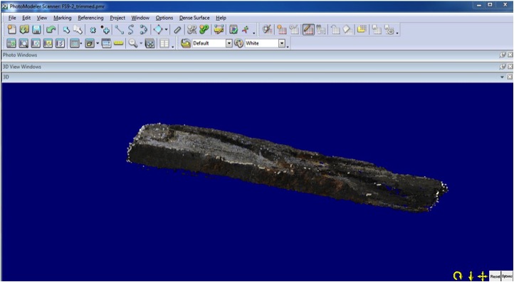
Figure 4: 3D model of a timber created in PhotoModeler Scanner.
STEP 2: Generate 3D data. The photographs were then used to create a 3D model in PhotoModeler Scanner by first creating cloud data of the timber and then transforming the cloud data into a triangulated mesh. This mesh recorded the curves of the timbers and was exported into the NURBS modeling software Rhinoceros.
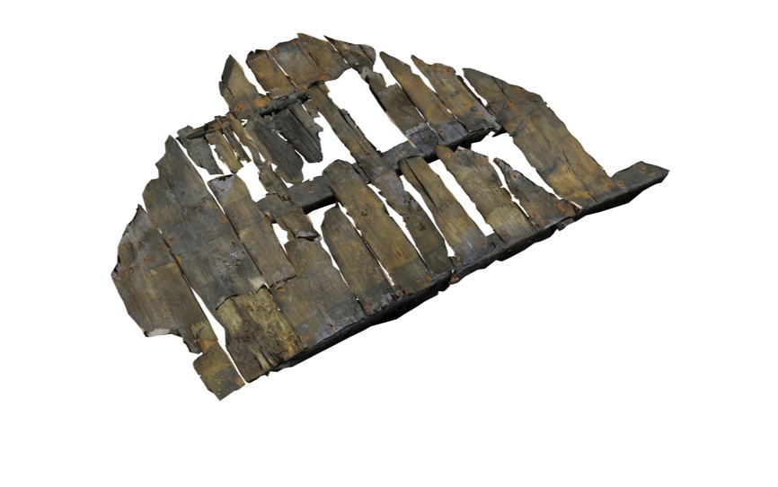
Figure 5: Reconstruction of the small deck.
STEP 3: Render into a model. Using Rhinoceros, a 3D image was created and nails were added following the locations of preserved nails. From this model, individual drawings can be produced to link the timber to information from field notes and examination in the lab. Additionally, these individual pieces were combined digitally in Rhinoceros to reconstruct the ship, using the aid of data from the laser scan.
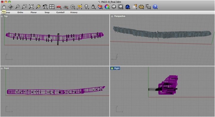
Figure 6: Reconstruction of a frame in Rhinoceros.
The emphasis for us was integrating three-dimensional recording techniques with traditional measuring and documentation techniques to quickly and accurately record the ship and enable analysis when access to the actual timbers may not be possible. On the one hand, it is easy to see the benefits: it’s a fast process in the field, it preserves and records curves very well, it facilitates collaboration and dissemination of information with digital files that can be easily shared. On the other hand, we tend not to think about the costs associated with it: digital cameras with high resolution files requiring terabytes of storage, the possibility of having corrupt hard drives, and long hours and tedious manual work to render the digital data into final forms. Most significantly, while advances in digital technology enable better documentation, will these advances make our early attempts obsolete? For example, the version of PhotoModeler Scanner that we used has already been updated, no longer requiring stereo-photographs. Using the photographs from the World Trade Center Ship, I am eager to try rendering models using newer versions of software to see what these changes might mean for our data. However, what would happen if I could no longer open the software used to access the data?
The power of photogrammetric techniques lies in their integration with traditional techniques, using them alongside measurements and drawings to record the archaeological data. While it’s a helpful tool, we still need to future-proof our data. From the 3D models, we can still produce standard drawings and take measurements. By supplementing recordings in the field and tape measurements, this redundancy can help catch errors in recording while producing a complete visual record of the object.
While moving forward with new technologies and digital recording procedures, are we at risk of advancing too quickly? Is there a risk that we will no longer have the computer programs or software to open these files and thus render our documentation obsolete? Or, is this a way of ‘future-proofing’ our data?
ACKNOWLEDGEMENTS
Archaeologists at AKRF, INC., Diane Dallal, Michael Pappalardo, Elizabeth Meade, and Molly McDonald, managed the excavation of the site for the Lower Manhattan Development Corporation (LMDC). The principle investigation of the ship was led by Warren Riess (University of Maine) and Carrie Fulton (Cornell University). Drawings were made by Kathleen Galligan. Drew Fulton (Drew Fulton Photography) photographed onsite panoramas and the timbers for photogrammetry. Timbers were initially stored at the Maryland Archaeological Conservation Laboratory and are now held in the Conservation Research Laboratory at Texas A&M University. The LMDC and the Port Authority of New York & New Jersey provided funding for this project.
Tech Week: Photography in Archaeology by Jonathan Libbon
Going Interactive Underwater by Drew Fulton
Preservation Photography: Roles and Rules by Karen Price
Interesting stuff. A few comments; I’m not convinced about the ‘traditional’/digital split, both are now merged, if we want to share a hand drawn sketch, we probably do so by making a digital copy of it. With regards to the negative aspects of digital documentation, these are now well understood, see guidance from the Library of Congress or Jisc Digital Media. Working digitally we must ensure that our work is justified and repeatable (just like non-digital archaeology) by keeping careful documentation, we must favour open software which has less risk of obsolescence and we must expect digital storage to fail and so make multiple copies. Having said all this, I’m sure the concerns in this report are very real and very common.
Clicking on this link — during the construction at the World Trade Center site in July 2010 — takes you to the discovery store. Has someone hacked the site?